Step 1 Remove the wires from the positive and negative terminals on the coil using a wrench to remove the nuts from the studs. Clip one end of the spark tester service part number 19368 to the ignition cable and the other grounded to the cylinder head as shown below.
How To Test A Spark Plug Ignition Coil Yourmechanic Advice
Connection procedure - Distributor systems.
Ignition coil testing procedure. Plug a high tension HT pick-up lead into Channel A on the PicoScope clip the leads fly lead on a suitable earth and clip the HT clip on to one of the engines plug leads. In this video I show you exactly how you can quickly determine whether you have a bad ignition coil pack or not and what is the correct testing procedure to. Buy MAS Ignition Coil DG508 Motorcraft Spark Plug SP479 compatible with Ford 46L 54L V8 DG457 DG472 DG491 CROWN VICTORIA EXPEDITION F-150 F-250 MUSTANG LINCOLN MERCURY EXPLORER Set of 8.
Set the positive lead of the multi-meter in position where the spark plug would usually insert ensure it has made good contact. The 1980s ushered in the magic black box Magnetron ignition coil Briggs Strattons first truly electronic ignition system. The fixed ignition spark tester works great for self-energizing magneto and solid state electronic and battery-powered ignition systems with a standard-outputstock coil to see if the ignition system is adequate to make a strong spark but the adjustable ignition strength tester can be used to test and measure the voltage output of the.
The Ignition Coil. Testing a spark plug ignition coil. As such they are generally not a repairable item.
The ignition coil on a motorcycle serves to step up the relatively low battery voltage to the high voltage needed to fire a spark plug. The individual ignition coil by one running cycle of the engine generates one ignition spark. Specifically the ignition coil will not spark.
They should be tested as part of. We will not be covering distributor-style ignition systems that use just one coil. Routine checks on a coil are not necessary.
Therefore in individual ignition systems is required synchronization of coils work with position of a camshaft. The ignition coil in your vehicle sends electricity to the spark plugs and you might need to test the coil if your vehicle isnt starting or frequently stalls. Coils are generally a sealed water-tight component.
To use with a points style distributor additional resistance is needed to get to 30 OHMs. Like all CD ignitions they use a large capacitor to discharge 420-480 Volts to coil and coil will normally be connected to ground. Find out what the.
One winding is called the primary winding the other is the secondary. A working ignition coil will give a reading of between 25 5 k ohms. If you are testing Direct.
Place the negative lead onto the metal body of the ignition coil again ensuring it makes proper contact. Basic set of hand tools for removal of ignition coil Digital multimeter. The ignition coil is the unit that takes your relatively weak battery power and turns it into a spark powerful enough to ignite fuel vapor.
Ignition System Theory and Testing. Testing the Coil or Armature Clip one end of the spark tester service part number 19368 to the ignition cable and the other grounded to the cylinder head. The coil is probably the easiest thing to check and therefore the first thing to check when embarking upon ignition system troubleshooting.
The procedure for testing the coil is the same for every ignition coil out there but if your car has coil packs it may require a different procedure. Breaker point ignition systems for most small air-cooled engine manufacturers have totally disappeared over the last 20 years. Procedure to verify the reliability of the secondary ignition circuit.
In this step-by-step guide we will go over how to test whether an ignition coil is good or bad by examining the resistance using a digital multimeter. Testing a Spark Plug Ignition Coil in 7 Steps. Yes you will need a ballast resistor when using ACCEL Super Coil 140001 with a Accel Points Conversion Kit PNs 2010ACC 2020 or Mallory Unilite or Magnetic Breakerless Ignition Distributor.
For this particular reason and before you follow the test procedures in this tutorial you need to verify that the ignition coil IS NOT sparking by connecting a spark tester directly on the ignition coils tower and cranking the engine. How to perform the test. We use cookies to keep our products working properly improve user experience analyze site traffic through our analytics partners and serve targeted communications.
You can usually test your ignition coils by plugging a diagnostic machine like an ODB2 scanner into the port underneath the dashboard and turning it on. Fig1 Secondary ignition waveform. Testing the Coil or Armature Step 1.
You will need a 30 kV ignition test adapter available from your test equipment supplier. The main reason 12V wont be present at coil is because your MSD ignition is a Capacitive Discharge Ignition. For the sake of convenience however well refer to both designs as ignition coils in this article.
Although testing ignition coils can be tricky its doable if you have the tools and knowledge. Part 1 of 1. A typical coil-on-plug COP ignition coil.
Basic set of hand tools for removal of ignition coil such as safety goggles and insulated pliers. Disconnect this plug lead at the spark plug end and. These coils are called windings.
Inside a traditional ignition coil are two coils of wire on top of each other. The coil is probably the easiest thing to check and therefore the first thing to check when embarking upon ignition system troubleshooting.
How to test troubleshoot check a starter for correct operation. Test the positive battery cable negative battery cables and the starter solenoid.

Consider correcting the leak and replacing the starter before a malfunction occurs.
Testing a starter solenoid. Starter solenoids have three or four threaded electrical lugs that attach to the battery ignition switch. The starter solenoid works as a powerful electric relay. Starter Soaked With Oil.
I suggest one more test and this is to test the battery cable that attaches to the starter motor for corrosion. Symptoms of a bad starter solenoid. Starter test starter solenoid test starter motor testTroubleshooting diagnosis repa.
For the ISGBSG industry DV has proven testing systems already developed and installed. The starter solenoid should make a clicking sound while providing a 12-volt reading on the voltmeters display indicating that power is being routed from the starter button to the starter solenoid and relay. Promoting the Legend of the Ford Mustang.
Check these readings against manufacturers specifications. When activated through the control terminal the solenoid closes the hi-current electric circuit and sends the battery power to the starter motor. The starter solenoid is a fairly simple mechanism that transmits electrical current from the battery to the starter.
A good connection should have a voltage drop of 02 volts or less. The core is free to move in and out with a return spring on one end. If testing the starter circuit See Checking the starter circuit indicates a fault in the starter motor disconnect the battery and remove the motor from the car - complete with its attached solenoid if it is a pre-engaged type of motor.
X Research source Removing a starter with or without an attached solenoid must be done carefully -- including jacking up the vehicle -- to prevent damage or hazards. Established in 1990 Jumps is a leading manufacturer of specialised auto electrical products. Mustang Forums at StangNet.
ALL-MAKES 39MT STARTERS Are equipped with Over Crank Protection OCP - protects starter against thermal damage Are equipped with an Integral Magnetic Switch IMS - reduces voltage drop ensures the solenoid receives the maximum available voltage in all starting conditions DO NOT REMOVE THE IMS SWITCH WHEN INSTALLING THIS STARTER. To check the starter solenoid or relay connections connect the meter positive lead to positive battery terminal on the solenoid or relay and the meter negative lead to the starter motor terminal. A Community covering all Years of the Ford Mustang.
When the contacts inside the starter solenoid are bad youd hear a single click from the solenoid but the motor would not run even if the battery cables and the cable terminals are good. The electrical contact points inside the starter solenoid can also become pitted or burned. This usually means that your starter motor is bad and needs to be rebuilt or replaced.
The starter solenoid is a remotely mounted switch that energizes the engine starter motor. An oil-soaked starter likely has a short life remaining. ALL-MAKES 39MT STARTERS Are equipped with Over Crank Protection OCP - protects starter against thermal damage Are equipped with an Integral Magnetic Switch IMS - reduces voltage drop ensures the solenoid receives the maximum available voltage in all starting conditions DO NOT REMOVE THE IMS SWITCH WHEN INSTALLING THIS STARTER.
The starter is often located around the bottom of the engine. A multimeter is needed to test and verify the problems of the starter solenoid but before the testing the following table can be used to determine whether the starter solenoid works. Its common to perform a voltage drop test on the starter circuit.
A starter solenoid is usually bigger than the starter relay. Crank the engine and note the reading. Flip the engine stop switch to the Off position to stop the engine then flip it back to the Run position if the engine successfully.
In addition to a global reach spanning 50 countries the company also caters to the Indian OE segment and aftermarket offering a diverse portfolio of products comprising Starter Motors Alternators and related electrical components. This can be accomplished very easily with a voltage drop test. DV is the 1 supplier of starter and alternator testing systems.
Voltage Drop Testing The Battery Cable. When you turn the key the solenoid engages using the electrical motor in the starter to get your engine running. Jumps Auto Industries Limited.
This can be helpful if the starter is completely dead not clicking or anything and can help diagnosis a wiring issues with the vehicle or a dead solenoid. At the same time the starter solenoid pushes the starter gear forward to mesh with the ring gear of the engine flexplate or flywheel. The other end is where current enters the solenoid and contains the various connectors.
This is because a voltage drop test is the best way to find resistance in a high current circuit. On page 14 of this instuctable there is a guide to testing the starter motor this can be done on the car if you can get to the back of the starter. Youll need to carefully disconnect the starters wiring unbolt it and remove it from the engine block to do further testing.
And is vulnerable to soaking from leaks. The solenoids internal construction consists of two coils of wire and a magnetic core towards one end. These are complete systems for the advanced testing of Electric and Hybrid Vehicle motors inverters batteries and E-axles.
If voltage drop is under max connect regulator lead and re-polarize generator. This is the 5V 1500mA DC regulator circuit.
Diagnosing a faulty AVR is done by a process of elimination.
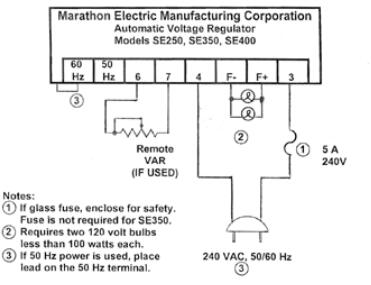
Generator voltage regulator testing. 25 LINE RING VOLTAGE BOOSTER - RING GENERATOR MODULE. Part DSI9P 25 LN RING VOLT BOOST-5 LN GEN 5495. Start by testing the generators main circuit breaker.
The generator set is available listed to UL 2200 Stationary Engine Generator Assemblies for all 60 Hz low voltage models. The IC is capable of delivering up to 1A of output current. You can find devices called LDOs or low dropout regulators with a voltage drop of around 04V since they use a MOSFET switch.
To ensure the voltage configuration is exactly what you need you should always consult an electrician or electrical contractor. For the ISGBSG industry DV has proven testing systems already developed and installed. From generator F to regulator F should not exceed 005 volts.
The PowerCommand control is Listed to UL 508 - Category NITW7 for US. The AC output lead wire leads from the voltage regulator to the stator. 25 Line Ring Voltage Booster Ring Voltage Generator Supports ringing for up to 5 Ring Voltage Booster Modules.
How to Test a 12V 7AH Battery. Which is a simple circuit using IC-7805 to the fixed regulator 5 volts and TIP41-NPN power transistor to increase current up to 2A. How to Charge a Battery with a Generator.
The regulator provides voltage to the exciter field resulting in a build-up of generator terminal voltage. Signs of a bad voltage regulator in a vehicle include dimming or pulsing lights or a dead battery. -40C TJ 125C IO 500mA VI 14V CI 033µF CO 01µF unless otherwise specified.
The AVR is a circuit that regulates and balances the amount of voltage being output from the generator. Digital Voltage regulator DVR It shall be confirmed 24V DC is available for the digital voltage regulator. This generator set is designed in facilities certified to ISO 9001 and manufactured in facilities certified to ISO 9001 or ISO 9002.
Some circuits based on LM317 voltage regulator. A voltage regulator will limit the maximum amount of voltage from a power source and prevents a device or alternator from shorting and overheating. Voltage between any single phase and neutral will be 277 VAC.
LM317 is a three terminal voltage regulator IC from National Semiconductors. USB Buck Boost Converter DROK DC-DC 35V-12V to 10-24V Step Up Down Voltage Regulator 5v 9v Power Supply Module 0-35V 0-3A Volt Current Power Display Meter Add to Cart Customer Rating. The battery charge lead runs form the voltage regulator to the positive side of the battery.
Input voltage can be up to 40V and output voltage can be adjusted from 12V to 37V. DV is the 1 supplier of starter and alternator testing systems. Troubleshooting 12 Volt Auto.
I use the 7805 power supply with the 12V battery. Voltage requirements can vary greatly for different types of equipment for example other voltage options include. These are complete systems for the advanced testing of Electric and Hybrid Vehicle motors inverters batteries and E-axles.
Our experienced staff can change generator output voltage generator must be equipped for change. Just as electrical systems powered by an alternator 6-volt systems require a voltage regulator to prevent the battery and generator from burning up light bulbs blowing fuses and melting the electrical system. The programmable parameters shall be set to the default values as recommended by the manufacturer.
The successive CE junctions add up to a voltage drop of around 2V across the regulator. This voltage is known as the dropout voltage the voltage below which the regulator quits regulating. Per ANSIRVIA EGS-1 and CSA-certified per Electrical Bulletin 946 This generator set was designed and manufactured in facilities certified to ISO 9001 60 Hz models meet applicable US.
All AVRs will have an adjustment screw which allows for the fine-tuning of the voltage output. Changing Voltage If the generator features a voltage select switch do not need a hardwire configuration performed. Abnormal fluctuation of the ammeter while testing the charging circuit indicates oxidized regulator points.
220 440 2400 3300 6900 11500 and 13500 How to determine Your Required Voltage. Testing the generator and regulator on a 6-volt electrical system is not difficult. The generator shall be started the view parameters the status of the switch parameters shall be recorded.
5 needed per 25 Line Ring Voltage Booster. Step-by-Step Instructions for Testing Your Harleys Charging System. To reduce the constant voltage of 5 volts.
EPA and California emissions standards. This system of using residual magnetism eliminates the need for a special field flashing circuit in the regulatorAfter the generator has established the initial residual voltage the regulator provides a controlled DC. Whether its an inspection or a repair MDA will design the solution you need to address your specific fleet issues and keep you running efficiently.
If you have electrical equipment that wont turn on that could. If we need to use 12V to 5V voltage regulator. MDA offers gas turbine services ranging from Combustion Hot Gas Path and Major Inspections as well as Compressor Turbine Rotor Repairs to Plant Performance Testing and Analysis.
Voltage regulators are commonly found in vehicles and other electronic equipment. All tests are conducted from the battery. Few useful circuits using the voltage regulator IC LM317 is shown here.
10 LM78XXLM78XXA 3-Terminal 1A Positive Voltage Regulator Electrical Characteristics LM7808 Continued Refer to the test circuits. If higher readings are obtained there is high resistance in the circuit.
Featured Post
wonderful quotes from it's a wonderful life
The 50 Most Wonderful Quotes from It's a Wonderful Life . Zuzu Bailey quotes 1. "Every time a bell rings, an angel gets his w...

